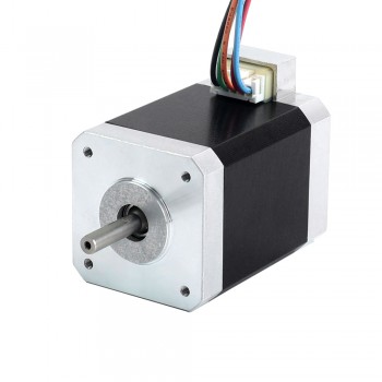
1.Definition of integrated stepper motors
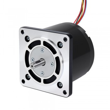
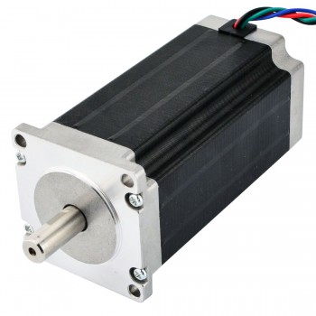
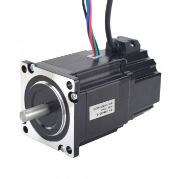
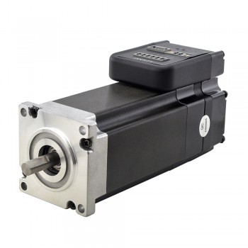
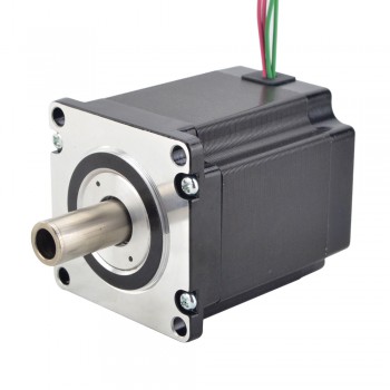
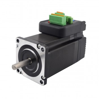
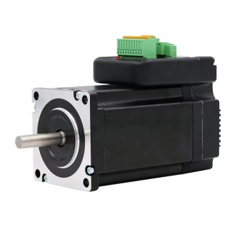
An integrated stepper motor is a motor product that integrates the driver and the motor body. It achieves a high degree of integration of the motor and the driver by directly embedding the drive circuit into the motor. This design greatly simplifies the installation process, reduces maintenance costs, and has significant advantages in space-constrained applications due to its compact structural design.
2.Working principle of integrated stepper motors
The working principle of integrated stepper motors is to convert electrical pulse signals into corresponding angular displacement or linear displacement. For each input pulse signal, the rotor rotates an angle or moves forward one step, and its output angular displacement or linear displacement is proportional to the number of input pulses, and the speed is proportional to the pulse frequency. Therefore, stepper motors are also called pulse motors.
3.Performance parameters of integrated stepper motors
1.Voltage range and maximum pulse response frequency: Integrated stepper motors usually have a wide voltage range. For example, the voltage range of the YSS60-P integrated closed-loop stepper motor is DC24V~50V, and the maximum pulse response frequency can reach 400KHZ.
2. Speed and torque: The speed and torque of the integrated stepper motor are its important performance indicators. For example, the maximum speed of the YSS60-P integrated closed-loop stepper motor can reach 3000rpm, and the high-speed torque attenuation is small, which can effectively improve the high-speed performance and torque utilization rate of the stepper motor.
3. Subdivision technology: Subdivision technology is one of the important characteristics of stepper motors. By controlling the current in each phase winding, they rise or fall according to a certain rule to form multiple stable intermediate current states, thereby improving the motor’s angular accuracy and running smoothness. For example, the YSS60-P integrated closed-loop stepper motor supports 16-speed subdivision.
4. Intelligent current regulation: Integrated stepper motors usually have the function of intelligent current regulation, which can reduce vibration, noise and heat generation and improve efficiency. For example, the YSS60-P integrated closed-loop stepper motor improves efficiency by 35% by intelligent current regulation.
5. Alarm and monitoring function: Some integrated stepper motors also have built-in in-position and alarm output signals, which are convenient for the host computer to monitor and control. For example, the YSS60-P integrated closed-loop stepper motor has built-in in-position and alarm output signals to ensure the safe operation of the processing equipment.
4.Precautions for the operation of integrated stepper motors
1. Power supply voltage and grounding method: Before operating the stepper motor, be sure to check whether the power supply voltage is appropriate and ensure that the positive and negative polarity of the DC input is correct. In addition, the grounding method is also very important. You can use a floating grounding method to avoid interference.
2. Check the connection: Before powering on, check whether the power cord, control signal line, etc. are firmly connected. Especially when used in industrial sites, it is recommended to use twisted pair cables to reduce interference.
3. Motor fixation: The stepper motor needs to be fixed during operation to avoid loss of step caused by resonance. If the motor is not fixed, strong resonance may occur, affecting the normal operation of the motor.
4. Debugging and operation observation: After connecting the circuit and setting the parameters, debug the stepper motor. Observe the operation of the motor, such as whether the action is normal and whether the temperature rises. If any problem is found, stop adjusting immediately.
5. Maintenance and care: Regularly check the connection and fixation of the stepper motor and the driver to ensure that there is no looseness or damage. At the same time, clean the dust and dirt on the surface of the motor and the driver to maintain good heat dissipation.
6. Control strategy selection: Select the appropriate control strategy according to the application requirements. Common control strategies include single-step control, micro-step control and vector control. Single-step control is suitable for basic rotation functions, micro-step control is suitable for high-precision positioning and smooth operation, and vector control is suitable for applications with high performance and high reliability requirements.
7. Prevent loss of step and noise: When running under high load or high speed, the stepper motor can be ensured not to lose step by gradually increasing the speed and frequency, while also reducing noise and improving accuracy.
Source:https://steppermotor2.hatenablog.com/entry/2025/04/21/182247