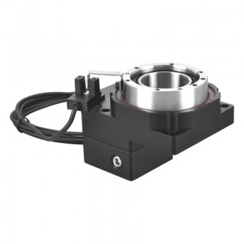
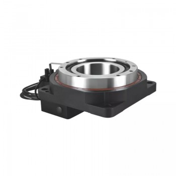
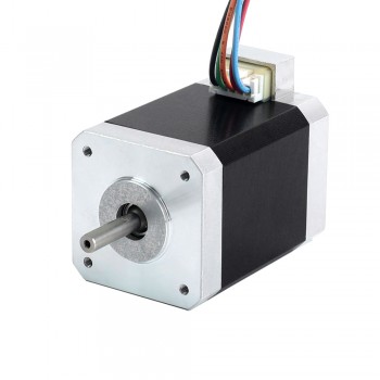
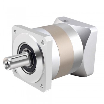
Noise reduction measures and uses of planetary gearboxes

1.Definition of planetary gearboxes
A planetary gearbox is a device that uses a planetary gear mechanism to achieve speed change and power transmission. A planetary gearbox consists of three main components: a sun gear, a planet carrier, and a ring gear. These components can be connected to different power input or output ends. A planetary gear refers to a gear system that can rotate around its own rotation axis like a fixed-axis gear, and its rotation axis also rotates around the axis of other gears with the planet carrier. By adjusting the fixed or moving state of these components, a variety of transmission methods can be achieved.

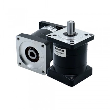
‌‌TQEG Series Nema 34 Planetary Gearbox 5:1 Backlash 15 Arcmin for Nema 34 Motor

2.Transmission principle of planetary gearboxes
The transmission principle of a planetary gearbox is different from that of a fixed-axis gear. Due to the existence of a planet carrier, there can be three rotating shafts that allow power input and output, and means such as clutches or brakes can be used to limit the rotation of one of the shafts when necessary, leaving only two shafts for transmission. The sun gear drives the planetary gear through the power of the input shaft, and at the same time drives the internal planetary gear, and finally outputs power through the ring gear. This structure has a strong torque amplification factor, which can increase the torque of the input shaft, thereby providing a greater torque output.

3.Noise reduction measures for planetary gearboxes
1.Improve gear accuracy: The accuracy level of gears directly affects their noise level. Compared with gears with low accuracy, gears with high accuracy can not only reduce transmission errors, but also significantly reduce noise. This can be achieved by improving the machining accuracy of gear holes, controlling the end face runout and radial runout of tooth blanks, and optimizing the gear cutting process.
2.Optimize gear design: Increasing the width of gears can reduce unit loads and reduce gear tooth deflection, thereby reducing noise. Using small pitch and small pressure angle can increase gear tooth contact overlap, improve transmission accuracy, and reduce noise. Reasonable selection of displacement coefficient can improve the bearing capacity and service life of gears, while effectively controlling noise.
3.Adjust speed change and transmission: Appropriately reducing the operating speed of the power source can effectively reduce noise. In multi-stage transmission, minimize the instantaneous transmission ratio change to ensure smooth transmission, reduce impact and vibration, and thus reduce noise.
4.Strengthen the box structure: The use of cylindrical boxes can reduce vibration and noise better than other types of boxes. Find the resonance position through resonance testing, and add ribs or plates to increase the rigidity of the box and reduce vibration. In addition, damping materials such as foam plastics can be placed on the surface of the box to reduce the noise of the reducer.
5.Improve lubrication conditions: Ensure that the gears in the reduction box are well lubricated. Use suitable lubricating oil and replace it regularly to reduce friction and noise. Reasonable lubrication methods and lubricant selection can also effectively reduce noise.
6.Manufacturing and assembly quality: Ensure the quality of raw materials, select high-quality steel and conduct strict chemical composition inspection, grain size determination and purity assessment. Control deformation during heat treatment to improve the quality of tooth processing. During assembly, pay attention to the centering of the gears, clearance adjustment and the tightness of fasteners to ensure the normal operation of the reduction box.

PX86 Planetary Gear Speed Reducer for Nema 34 Stepper Motor / Servo Motor

4.Uses of planetary gearboxes
1.Industrial machinery and equipment: Planetary gearboxes play an important role in industrial machinery and equipment, especially in applications requiring high torque density. They can distribute torque and power in a compact form and are suitable for various heavy machinery and engineering vehicles.
2.Automation devices: In automation devices, planetary gearboxes are used to drive and control various automation equipment, such as automatic curtains, smart toilets, lifting systems, etc. These applications require smooth operation and large load-bearing capacity of the equipment, and planetary gearboxes just meet these needs.
3.Transportation: In the field of transportation, planetary gearboxes are often used in automobile transmissions to provide smooth shifting and transmission effects. In addition, they are also used in equipment such as wind power generation and pump compressors to ensure stable operation and efficient transmission of equipment.
4.Robotics: With the rapid development of automation and robotics, high-precision planetary gearboxes play a key role in robot joint drive and end effector control. They improve the performance and efficiency of robots and are widely used in various automation systems.
5.Other fields: Planetary gearboxes are also used in the food industry, medical technology, and pharmaceuticals to improve the performance and efficiency of equipment. For example, in medical devices, planetary gearboxes can provide stable transmission effects and ensure precise operation of equipment.

Similar articles:https://steppergoods.muragon.com/entry/6.html

Braking methods and advantages of brake stepper motors

1.Basic definition of brake stepper motors
Braking stepper motors are stepper motors with brake functions, mainly used to control brakes and transmission systems. It consists of a stator, a rotor and a brake device. The stator is covered with an electromagnetic coil. When the coil is excited by current, a magnetic field is generated to attract the rotor to step. The brake device is used to control the braking and release of the motor to ensure that the motor can remain in the desired position when it stops.

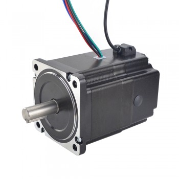
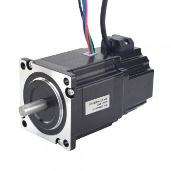
Nema 34 Stepper Motor P Series 1.8 Deg 4.5Nm/637.38oz.in 6.0A 2 Phase with Electromagnetic Brake

2.Braking methods of brake stepper motors
‌1.Short-circuit method: By short-circuiting the two phases of the motor, the motor loses its driving force, thereby achieving the purpose of braking. This method is simple and easy to operate, and does not require additional circuits, but the braking time is long and it is easy to cause the motor temperature to rise, which is not suitable for long-term use.
‌2.Back electromotive force method: A reverse voltage is added between the two phases of the motor to prevent the motor from rotating. This method has a short braking time and will not cause the motor to overheat, but it requires additional circuits, and the reverse voltage may damage the motor.
‌3.Current cut-off method: By cutting off the current of the motor, the motor loses its driving force. This method has a short braking time and good braking effect, and will not cause the motor to overheat, but it requires additional circuits, and the timing of current cut-off needs to be mastered accurately.
‌4.Electromagnetic braking method: The stepper motor itself has a holding torque, which can lock the motor when powered on. If the holding torque of the stepper motor is not large enough, or the holding torque is lost after a power outage, you can consider using a stepper motor with a brake. The brakes of stepper motors are generally spring-type and permanent magnet-type. Permanent magnet brake stepper motors have fast response speed, low noise, and less heat.

3.Advantages of brake stepper motors
‌1.High-precision stepper control: The brake stepper motor can accurately control the rotation angle and speed of the motor by inputting a specific pulse signal to the motor. This is very important for applications that require precise positioning and fine control, such as printers, CNC machine tools, and automotive braking systems.
2.Low noise and reliability: The brake stepper motor generates low noise during operation, and due to its design and working principle, it has high reliability and can operate stably in various industrial and consumer products.
‌3.Low power consumption and small size‌: Braking stepper motors have low power consumption and small size, which makes it easy to embed and apply in most devices‌.
‌4.Fast, smooth and accurate braking performance‌: Braking stepper motors stop the rotor through the friction between the brake disc, brake key and brake pad, and are suitable for occasions that require fast stopping or accurate positioning, such as automation equipment, robots, CNC machine tools and other industrial fields‌.
‌5.High efficiency and good low-speed characteristics‌: Braking stepper motors can quickly accelerate, decelerate and reverse motion, have high efficiency, and perform well at low speeds, ensuring the reliability and long life of the equipment‌.
‌6.Used in conjunction with a driver‌: Braking stepper motors are usually used with a driver, which can provide corresponding current and pulse signals according to the set step and speed parameters, thereby accurately controlling the movement of the motor‌.
‌7.Special control functions can be realized‌: Some advanced braking stepper motors can also realize closed-loop control, by installing encoders and sensors to feedback the actual position and rotation angle of the motor, further improving the control accuracy and stability‌.

Nema 23 Stepper Motor P Series 1.8 Deg 1.2Nm/169.97oz.in 4.0A 2 Phase with Electromagnetic Brake

‌4.Main application scenarios of brake stepper motors
‌1.Automobile field: Brake stepper motors play an important role in automobile braking systems. By receiving control signals and driving actuators, they can achieve precise deceleration or parking of the car.
‌2.Two-wheeled vehicles such as bicycles and scooters: The brake systems of these vehicles are usually equipped with brake stepper motors to ensure safety and control speed during driving.
‌3.Industrial equipment: Many industrial equipment require the use of precise control systems, such as CNC machine tools and printing presses. Brake stepper motors can help realize the automatic control and adjustment functions of equipment.
‌4.Aerospace field: Brake stepper motors also play an important role in some high-precision instruments and equipment, such as astronomical telescopes and radar systems.
‌5.Hoisting machinery: In equipment such as cranes and winches, brake stepper motors can brake immediately in the process of lifting or lowering the load, once a fault or abnormality occurs, to prevent heavy objects from falling and ensure the safety of personnel and equipment.
‌6.Elevator system‌: Provide reliable braking protection for the up and down movement of the elevator, ensure that the elevator is accurately in place when it stops, and quickly brake in an emergency to avoid accidents.
‌7.Automated production line‌: On an automated production line, when a link fails or an emergency shutdown is required, the brake stepper motor can quickly stop the operation of related equipment to prevent product damage, equipment collision, etc., and reduce production losses.
‌8.Stage machinery‌: In stage lifting, translation and other equipment, the brake stepper motor can ensure the safety of actors and equipment and avoid accidents.

Classification and selection principles of servo motors

1.Definition of servo motors
The definition of servo motors is an engine that controls the operation of mechanical elements in a servo system. It is an auxiliary motor indirect speed change device. The main function of a servo motor is to convert the input voltage control signal into the angular displacement and angular velocity output on the shaft to drive the control object. Its biggest feature is that it can rotate immediately when receiving the control signal and stop immediately when the signal disappears. The servo motor has the characteristics of small electromechanical time constant, high linearity, and starting voltage, and can convert the received electrical signal into angular displacement or angular velocity output on the motor shaft.

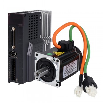
400W 交流伺服电机套件 3000rpm 1.27Nm 带伺服驱动器和 17 位编码器 IP65 E6 系列

2.Classification of servo motors
1.DC servo motors are powered by a DC power supply and achieve precise control of the motor by controlling the current size and direction. It is usually composed of an armature, a magnetic pole, a permanent magnet or a winding. DC servo motors have high speed and torque, fast response speed, and high control accuracy. They are suitable for industrial automation fields with high-precision control, such as CNC machine tools, printing machines, packaging machines, etc. However, due to the presence of brushes and brush rings, long-term operation may cause brush wear, affecting the performance and life of the motor. 2. AC servo motors are powered by AC power and have high speed and torque. They are usually composed of permanent magnets and stator windings, and the speed and position of the motor are controlled by the frequency and phase of the AC power supply. AC servo motors have the characteristics of simple structure, brushless commutation, and long life, and are suitable for fields with high-precision control and high-power output, such as wind turbines, rail transportation, etc. In addition, AC servo motors also have good dynamic performance and anti-interference ability, and can meet the working requirements in various complex environments.

3.Common causes of servo motor alarms
1.Excessive load: When the load driven by the servo motor exceeds its carrying capacity, the motor will not work properly and may trigger an overload alarm. This may be caused by reasons such as excessive load itself, failure of the transmission mechanism or mechanical components.
2.Power supply problem: unstable power supply voltage or poor contact of the power supply line may cause the servo drive to alarm. Too high or too low power supply voltage will affect the output power and stability of the motor, which will lead to an alarm.
3.Control system problem: Improper parameter settings of the control system, control signal interference or control line failure may cause the servo drive to alarm. For example, improper parameter settings, abnormal control signals, etc.
‌4.Drive hardware failure: Damage to the power module, control board, sensor and other hardware inside the servo drive will also cause an alarm. For example, power transistor damage, encoder failure, etc.
‌5.Mechanical failure: Wear, looseness, and jamming of mechanical parts may also cause servo drive alarms. For example, bearing damage, insufficient lubrication, etc.

短轴 NEMA 23 集成简易伺服电机 180w 3000rpm 0.6Nm(84.98oz.in) 20-50VDC 57 x 57 毫米

4.Selection principles of servo motors
1.Performance matching principle: The selection of servo motors must first meet the performance requirements of automation equipment, including output power, speed range, positioning accuracy, response speed and other indicators. When selecting, it is necessary to comprehensively consider the load characteristics, operating environment and working requirements of the equipment to ensure that the selected servo motor can meet the needs of actual applications.
‌2.Stability principle: The servo motor needs to have stable operating characteristics during work to ensure the stable operation of the automation equipment. Therefore, when selecting, it is necessary to pay attention to the output stability, temperature rise characteristics, anti-interference and other indicators of the servo motor, and select products with stable performance and high reliability.
‌3.Economic principle: On the premise of meeting performance and quality, the selection of servo motors also needs to consider cost factors. Engineers and technicians need to comprehensively consider factors such as the cost, maintenance costs, and energy consumption of servo motors, and select products with high cost performance to reduce the overall cost of automation equipment.
‌4.Reliability principle‌: As an important component of mechanical transmission, the reliability of servo motors is directly related to the stable operation of automation equipment. Therefore, when selecting, it is necessary to select products with reliable quality and stable performance to avoid using inferior products to damage the equipment.
‌5.Applicability principle‌: The selection of servo motors also needs to consider their scope of application and use environment, such as dust and water resistance, explosion-proof function, operating temperature range, etc. When selecting, it is necessary to select suitable products according to actual working conditions to ensure that the servo motor can work stably in a specific environment.

Source:https://steppermotor2.hatenablog.com/entry/2024/10/11/175540

Ventajas y campos de aplicación de los motores paso a paso de eje hueco

1.Definición simple de motor paso a paso de eje hueco
El motor paso a paso de eje hueco es un tipo especial de motor paso a paso. Su estructura interna adopta un diseño hueco y se compone principalmente de imanes, marcos internos y externos, cojinetes, bobinas y otras partes. ‌Este tipo de motor tiene las ventajas de alta densidad de potencia, tamaño pequeño, alta eficiencia, bajo nivel de ruido, bajo aumento de temperatura y alta confiabilidad, por lo que tiene importantes aplicaciones en los campos aeroespacial, militar, automovilístico, médico, robótico y otros. El diseño del motor paso a paso de eje hueco optimiza en gran medida el diseño mecánico, facilita el cableado y ahorra espacio de diseño y costos de producción. El orificio interior se utiliza principalmente para cableado, transmisión de luz u otros medios como el aire. Este diseño no solo es adecuado para ocasiones en las que la precisión dimensional del eje hueco del motor paso a paso o del orificio interior no es alta, sino también debido a. Su estructura simple, funcionamiento confiable y fácil de mantener, es ampliamente utilizado en diversos campos industriales, como maquinaria de plástico, maquinaria de impresión, maquinaria textil, etc.

Nema 14 双空心轴双极步进电机 1.8 度 16 Ncm 1.25 A 4 线

2.Proceso de trabajo del motor paso a paso de eje hueco
El proceso de trabajo del motor paso a paso de eje hueco se basa principalmente en la conversión de señales de impulsos eléctricos en el correspondiente desplazamiento angular o desplazamiento lineal. El principio de funcionamiento de este tipo de motor es convertir la señal de pulso eléctrico de entrada en movimiento mecánico. Cada vez que se ingresa una señal de pulso, el rotor girará un ángulo fijo o avanzará un paso. El desplazamiento angular o lineal de salida es proporcional. Al número de pulsos de entrada, la velocidad de rotación es proporcional a la frecuencia del pulso. La rotación del motor paso a paso de eje hueco se realiza paso a paso en un ángulo fijo (llamado “ángulo de paso”). Al controlar el número de pulsos, se puede controlar el desplazamiento angular para lograr un posicionamiento preciso. Al mismo tiempo, al controlar la frecuencia de los pulsos, se puede controlar la velocidad y la aceleración de la rotación del motor para lograr el propósito de regular la velocidad. El principio de funcionamiento de este tipo de motor utiliza circuitos electrónicos para convertir la corriente continua en una corriente controlada por secuencia multifásica que se alimenta en parte para alimentar el motor paso a paso. El controlador del motor paso a paso es un componente clave. Suministra energía de tiempo compartido al motor paso a paso y controla la sincronización multifásica para garantizar que el motor pueda funcionar normalmente.

3.Ventajas de los motores paso a paso de eje hueco
‌1.Optimizar el diseño mecánico‌: El diseño del motor paso a paso de eje hueco permite un orificio hueco en el centro del eje. Esta estructura permite que la dirección axial penetre en el espacio, logrando así un diseño más compacto y optimizado en el diseño de la máquina. Este diseño no solo optimiza la estructura mecánica, sino que también permite la transmisión de materiales, señales, luz, etc. a través del espacio axial, mejorando la eficiencia y el rendimiento general del dispositivo‌.
‌2.Cableado conveniente‌: la estructura hueca del motor paso a paso de eje hueco facilita el cableado y puede evitar la distorsión y el daño del cable. Esta característica es particularmente importante en escenarios de aplicaciones que necesitan transmitir cables, alambres y señales de sensores. Este diseño no solo simplifica el proceso de cableado, sino que también mejora la confiabilidad y mantenibilidad del equipo.
‌3.Ahorre espacio de diseño y costos de producción‌: debido al pequeño tamaño del motor paso a paso de eje hueco, el diseño de alta densidad de potencia puede ahorrar espacio, mejorando así la utilización de energía. Al mismo tiempo, su diseño de alta eficiencia reduce el peso del motor, aumenta el espacio del circuito magnético, aumentando así la densidad de potencia, reduciendo el ruido y el aumento de temperatura, lo que reduce directamente los costos de producción.
‌4.Adaptarse a una variedad de escenarios de aplicación‌: los motores paso a paso de eje hueco se utilizan en una amplia gama de aplicaciones, incluidos equipos de automatización, equipos médicos, equipos de impresión, maquinaria textil, equipos de escenario, aeroespacial, ingeniería de vehículos, etc. En estos campos, los motores paso a paso de eje hueco pueden proporcionar un control preciso de la posición y del movimiento, al tiempo que facilitan el paso de cables, tuberías de aire, etc., mejorando la integración y confiabilidad del equipo.

Nema 23 双极步进电机 1.8 度 1.45 Nm 2.0A 双轴 4 线空心轴

4.Áreas de aplicación de los motores paso a paso de eje hueco
1.En términos de equipos de automatización, los motores paso a paso de eje hueco se utilizan ampliamente en robots, líneas de producción automatizadas, máquinas herramienta CNC, etc. para proporcionar un control de posición y control de movimiento precisos y al mismo tiempo facilitar el paso de cables, tuberías de aire, etc.
‌2.En el campo de los equipos médicos, los motores paso a paso de eje hueco se utilizan a menudo en robots quirúrgicos, equipos de imágenes médicas, equipos de automatización de laboratorio, etc., para cumplir con los requisitos de alta precisión y confiabilidad y para facilitar el trazado de cables y tráquea. , etc.
‌3.En los equipos de impresión‌, se utilizan motores paso a paso de eje hueco para impulsar componentes como rodillos de impresión y transportadores de papel para mejorar la integración y confiabilidad del equipo.
‌4.En maquinaria textil‌, los motores paso a paso de eje hueco se utilizan para accionar componentes como el bobinado de hilo y los telares, y también mejoran la integración y confiabilidad del equipo.
‌5.En términos de equipos de escenario, los motores paso a paso de eje hueco se utilizan para impulsar la elevación, la rotación y otros componentes del escenario para mejorar la integración y confiabilidad del equipo.
‌6.En el campo aeroespacial, los motores paso a paso de eje hueco se utilizan para accionar componentes como superficies de timón y trenes de aterrizaje para facilitar el paso de cables, tuberías de aire, etc., y mejorar la integración y confiabilidad de los equipos.
‌7.En la ingeniería de vehículos, los motores paso a paso de eje hueco se utilizan para accionar elevalunas eléctricos, ajustes de asientos y otros componentes para facilitar el paso de cables, tuberías de aire, etc., y mejorar la integración y confiabilidad de los equipos.
8.En la ‌automatización industrial‌ y la ‌robótica‌, los servomotores de alta velocidad y los motores paso a paso de eje hueco se utilizan para controlar con precisión los dispositivos mecánicos en las líneas de producción y lograr un control preciso del movimiento de las articulaciones de los robots.
‌9.En el campo de la fabricación inteligente, con el avance de la Industria 4.0, los servomotores de alta velocidad combinados con motores paso a paso de eje hueco se utilizan en campos emergentes como los vehículos de nueva energía y la logística inteligente, que requieren que los sistemas de motor tengan una potencia de salida eficiente. y capacidades de control adaptativo inteligente.

Fuente:https://steppermotor2.hatenablog.com/entry/2024/09/21/172019

Operation mode of integrated servo motor

1.Definition of integrated servo motor
Integrated servo motor‌ is a motor that integrates servo motor and driver. It has the characteristics of compact structure, easy installation and fast response speed. The integrated servo motor has a servo driver integrated inside it, which can directly receive signals from the controller and perform corresponding actions. Compared with traditional split servo motors, this design reduces the number of external connecting parts, further simplifying the installation and maintenance process of the system. In addition, due to the integrated design, the integrated servo motor also has significant advantages in performance, such as higher accuracy and faster response speed, thereby improving the overall performance and reliability of the system.

NEMA 24 Closed Loop Integrated Stepper Servo Motor 3Nm(425 oz-in) 24-50VDC 4.5A

2.Components of integrated servo motor
1.Motor part‌: including rotor, stator, windings, magnetic poles and other components. There are various types of motors, such as DC servo motors, AC servo motors, stepper servo motors, etc. Each type of motor is different in structure and control method.
2.Sensor part: usually includes position sensor, speed sensor, torque sensor, etc., which are used to detect the position, speed, torque and other parameters of the motor in real time, and feed the detection results back to the control system for real-time adjustment.
3.Controller part‌: Usually composed of a control chip, amplifier, encoder, etc., used to receive parameters fed back by sensors and output control signals to the motor to control and adjust the position, speed, torque and other parameters of the motor. .
4.Power supply part‌: Usually composed of power transformer, rectifier, filter, etc., used to provide stable power supply voltage and current to ensure the normal operation of the motor.
5.Mechanical part‌: Usually composed of reducers, couplings, transmission devices, etc., used to convert the rotational motion output by the motor into linear motion or other specific motion forms to meet different application requirements.

3.Operation mode of integrated servo motor
1.Position mode‌: This is the most commonly used control mode for servo motors. The host computer sends high-speed pulses of a certain frequency and cooperates with the direction signal to realize the forward and reverse rotation of the motor. By adjusting the frequency of the pulses, the speed of the servo motor can be changed. The core of the position mode is the position closed-loop control system, which consists of position sensors, controllers, drives and motors. It uses PID control algorithm to achieve precise control of the motor position by adjusting the proportional coefficient, integral coefficient and differential coefficient. Position mode is widely used in situations that require precise positioning, such as CNC machine tools, robot joints, automated assembly lines, etc.
2.Speed ​​mode‌: Speed ​​mode uses analog quantities to control the rotation speed of the motor. Although speed mode has fewer applications because it can control speed with the same accuracy as position mode, it still has its uses in certain specific applications. The core of speed mode is the speed closed-loop control system, which consists of speed sensor, controller, driver and motor. It also uses PID control algorithm to eliminate speed deviation and make the motor shaft run at a constant or changing speed.
3.Torque mode‌: Torque mode is usually used in constant voltage control to control the output torque of the servo motor through analog quantities. This mode is combined with the position mode for closed-loop control, and the effect is more ideal. The control of torque mode is more complicated, and it is necessary to detect the output current of the servo drive and perform torque control based on the current feedback signal.

Nema 23 Integrated Closed Loop Stepper Servo Motor 24-50V DC 2.2Nm 1000CPR ESS Series

4.Application scope of integrated servo motor
‌1.Industrial automation‌: Integrated servo motors play a vital role in the field of industrial automation and are widely used in robotic arms, conveyors, assembly lines and other equipment. They realize efficient production processes and improve production efficiency and product quality through precise position control and motion control. The fast response and precise position feedback capabilities of servo motors enable it to adapt to complex industrial environments and task requirements‌.
2.Robot technology‌: Servo motors are an ideal choice for robot joint drive. They can provide high-performance power output and flexible motion control to meet the different needs of robots in various industries, services and special environments. In fields such as automated production lines and logistics warehousing, servo motor-driven robots can achieve efficient operations and automation tasks‌.
3.CNC machine tools‌: Integrated servo motors are widely used in CNC machine tools, which can achieve precise motion control and position control, provide high-speed, high-precision working performance, and meet the needs of modern manufacturing for equipment automation and intelligence.
4.Medical equipment‌: Servo motors are widely used in various medical equipment, such as medical robots, imaging equipment, surgical instruments, etc. The high precision and reliability of servo motors play a vital role in medical equipment, ensuring the stability and safety of medical equipment‌.
5.Aerospace‌: In the field of aerospace, servo motors are widely used in the steering gear system of aircraft to achieve attitude control and flight stability of the aircraft by controlling the rudder surface of the aircraft. The rapid response capability and precise control capability of the servo motor enable the aircraft to achieve various complex flight movements, ensuring flight safety and stability‌2.

In addition, integrated servo motors are also used in medical equipment, 3D printing, textiles, printing and other industries. With the continuous development of technology, its application scenarios will continue to expand, providing more efficient and accurate solutions for various industries‌.

Source:https://www.steppernews.com/2024/08/operation-mode-of-integrated-servo-motor.html

Application fields and advantages of five-phase stepper motors

1.Definition of five-phase stepper motors
A five-phase stepper motor is a motor powered by a five-phase AC power supply. Its structure is more complex than that of a four-phase stepper motor, and it can provide higher control accuracy and finer step lengths. This type of motor is usually used in application scenarios that require high-precision control, such as precision CNC machine tools, high-precision robots and other equipment. The working principle of a five-phase stepper motor is to control the power-on sequence of the five windings and the magnitude of the current to make the rotor produce different rotation angles, thereby achieving precise position control. Due to the high precision of the five-phase stepper motor, it has been widely used in high-precision automation equipment.

Nema 17 步进电机 5 相 0.5Nm 0.72 度 1.8A 42x42x60mm 5 线

2.How to control the direction of the five-phase stepper motor
1.Change the direction of the current
The direction of the five-phase stepper motor can be achieved by changing the direction of the current. Usually, a five-phase stepper motor has two sets of coils, each with two pins, marked as A+, A- and B+, B-. If you want the motor to rotate clockwise, the current should enter the coil from A+ and B- and exit the coil from A- and B+; if you want the motor to rotate counterclockwise, the current should enter the coil from A- and B+ and exit the coil from A+ and B-.
2.Change the step sequence
Stepper motor control is actually controlling the step sequence of the motor. The step sequence of a five-phase stepper motor is AB-BC-CD-DE-EA. If you need to change the direction of the motor to the opposite direction, you need to change the step sequence. The method is to reverse the flow of current, that is, first energize the E and D coils, then energize the A and E coils, and so on.
3.Use a direction controller
If you don’t want to change the connection method or step sequence in the circuit, you can also use a direction controller to change the direction of the five-phase stepper motor. The direction controller can add a reversing switch at the input or output of the motor control signal. When you need to change the direction, just switch the switch.

3.Advantages of five-phase stepper motors
1.Smooth motion and high resolution: The five-phase stepper motor makes the rotation of the stepper motor smoother by introducing more phases, reduces vibration and noise, and improves the stability of the mechanical system. It can achieve a smaller step angle and improve the resolution of the stepper motor through microstepping, which is very useful for applications that require precise positioning and control.
2.Low speed and high torque: The five-phase stepper motor can provide higher output torque at low speed, which is very beneficial for some applications that require low speed and high torque output, such as medical equipment and precision instruments.
3.Reduce resonance and high-speed performance: At certain frequencies, stepper motors may resonate, resulting in unstable motion. Five-phase stepper motors can effectively reduce resonance and improve the smoothness of the system’s motion. At the same time, it can better control the motor at high speed and reduce the possibility of losing steps, which is very important for applications that require high-speed motion, such as printing presses and CNC machine tools. ‌
4.High efficiency: By better controlling the phase of the motor, the five-phase stepper motor can achieve the same output power at a lower current, thereby improving the energy efficiency of the system. ‌
5.Strong adaptability: The five-phase stepper motor driver is suitable for various stepper motors, including different types of motors such as bipolar, quadrupole and octapole, and has a wide range of applicability. ‌

5 相可变磁阻步进电机 3.2Nm(453.16oz.in)3A φ9mm 6 线 90 x 90 x 67mm

4.Application fields of five-phase stepper motors
1.Automation equipment and instruments: The five-phase hybrid stepper motor is suitable for various small automation equipment and instruments, such as pneumatic marking machines, labeling machines, cutting machines, laser marking machines, plotters, engraving machines, CNC machine tools and pick-and-place devices. In these applications, the five-phase stepper motor can provide low vibration, low noise, high precision and high speed performance to meet user needs. ‌2.Precision CNC machine tools and high-precision robots: Due to its high-precision characteristics, the five-phase stepper motor is widely used in high-precision automation equipment such as precision CNC machine tools and high-precision robots. These devices have high requirements for precision and performance. Five-phase stepper motors can provide finer steps and higher control accuracy to ensure accurate operation of the equipment.
3.Industrial automation, machine tools, printing presses: Five-phase stepper drives are mainly used in industrial automation, machine tools, printing presses and other fields, with precise angle and speed control as the main features. These application areas require stepper motors to provide stable and reliable operation and precise position control.
4.Textile machinery and equipment: Stepper motors are widely used in textile machinery and equipment, such as computer embroidery machines. In particular, five-phase hybrid stepper motors use high-phase stepper motors to reduce step angles and improve control accuracy. They are suitable for applications with smooth operation, low noise, fast response and long service life.

5.Conclusion
As a special stepper motor, the five-phase stepper motor has the advantages of high precision, high efficiency and low noise. Its working principle, circuit structure and control method are different from those of traditional stepper motors, but its application range is wider. In the future, with the continuous advancement of science and technology and people’s increasing demand for high-precision intelligent equipment, five-phase stepper motors are expected to be used in more fields.

Source:https://www.steppernews.com/2024/08/application-fields-and-advantages-of.html

Selection and maintenance methods of variable reluctance stepper motor

1.Definition
A variable reluctance stepper motor is a motor whose rotor is made of ferromagnetic material. When the stator is energized, it becomes an electromagnet and the rotor feels a pull in the specified direction. Ferromagnetic materials always try to adjust themselves in the path of minimum magnetic resistance. By energizing the coil, a magnetic field is generated and the air gap magnetic resistance is changed. This type of motor is called a variable reluctance stepper motor. In this type of motor, the direction of the motor is independent of the direction of the current in the winding. The rotor of a variable reluctance stepper motor (VR stepper motor) is made of soft magnetic material and has no permanent magnets. The stator coil generates a magnetic field that attracts the rotor teeth and causes the rotor to move step by step.

2.Common types of faults
1.Abnormal operation: This may be caused by improper driver parameter settings, poor connection between the motor and the driver, or motor failure. To solve this problem, you need to check whether the driver parameter settings are correct, whether the connection between the motor and the driver is good, and whether the motor is faulty.
2.Loss of step: This means that the actual position of the motor is inconsistent with the command position during operation. The reason for the loss of step may be due to excessive motor load, insufficient drive current, improper setting of the drive subdivision number, etc. The solution to this problem is to reduce the motor load, increase the drive current, adjust the drive subdivision number, etc.
3.Excessive noise: It may be caused by motor bearing wear, bad gears, poor connection between the motor and the drive, etc. In order to reduce noise, it is necessary to check the condition of the motor bearings and gears to ensure that they are in good working condition, and check whether the connection between the motor and the drive is good.
4.Heat: It may be caused by excessive motor load, excessive drive current, poor motor heat dissipation, etc. In order to avoid overheating of the motor, it is necessary to reduce the motor load, adjust the drive current, strengthen the heat dissipation of the motor, etc.

5 相可变磁阻步进电机 3.2Nm(453.16oz.in)3A φ9mm 6 线 90 x 90 x 67mm

3.Maintenance and maintenance methods
1.Cleaning: Clean the stepper motor regularly to remove dust and dirt and keep the motor clean. Use vinegar or gasoline to wipe the inside and outside of the motor, and pay special attention to protect the motor from physical damage
2.Lubrication: Lubricate the bearings and other moving parts of the stepper motor regularly to reduce friction and wear. ‌ Use special lubricating oil or grease, and ensure that the bearings are fully lubricated. ‌
3.Parts replacement: Regularly check the parts of the stepper motor, such as the synchronous belt, gears and controller, and replace them in time if they are damaged or aged. ‌ It is recommended to use original accessories to avoid incompatibility issues that may be caused by using non-original parts. ‌
4.Storage conditions: If the stepper motor is not used for a long time, it should be stored in a dry, dust-free environment to prevent moisture and dust from damaging the motor. ‌ During storage, it is recommended to turn the motor regularly to ensure its flexibility. ‌
5.Regular operation: Even if it is not used frequently, the stepper motor should be run for a period of time regularly to maintain its performance and flexibility. ‌ This helps prevent the motor from degrading due to long-term non-use. ‌
6.Avoid overload: Make sure the load of the stepper motor is within the recommended range and avoid long-term overload operation to prevent overheating and damage to the motor. ‌
7.Professional operation: It is not recommended to repair or adjust the stepper motor by yourself unless you are an experienced technician. You should seek the help of professionals to ensure proper maintenance and extend the service life.

4.How to choose the right model

1.Torque selection: Choose the right motor model according to the required torque size (i.e. the torque size of the object to be driven). ‌ Generally speaking, if the torque is below 0.8N.m, you can choose 20, 28, 35, 39, 42 (the diameter or squareness of the motor body, unit: mm); if the torque is around 1N.m, it is more appropriate to choose a 57 motor; if the torque is several N.m or more, you should choose a stepper motor with specifications such as 86, 110, 130, etc. ‌2.Speed ​​selection: The output torque of the motor is inversely proportional to the speed. At low speed, the output torque of the motor is large; while at high speed, the torque will decrease. ‌ Choose the right motor according to the needs of the working environment. If a high-speed motor is required, a motor with a slightly smaller inductance should be selected to obtain a larger output torque.
3.No-load starting frequency selection: The no-load starting frequency of the stepper motor is an important indicator, especially in applications that require instantaneous frequent starting and stopping. If you need to start directly to achieve high-speed operation, you should choose a motor with a higher no-load starting frequency, such as a reactive or permanent magnet motor.
4.Phase number selection: Motors with different phase numbers have different working effects. The more phases, the smaller the step angle can be made, and the vibration during operation is relatively smaller. In most occasions, two-phase motors are used more. However, in high-speed and high-torque working environments, three-phase stepper motors are more practical.
5.Use environment: Select according to the use environment of the motor. For example, special stepper motors that are waterproof and oil-proof are suitable for some special occasions, such as underwater robots, etc.

Design principles and common faults of waterproof stepper motors


1.Definition
The waterproof stepper motor is an electric device with waterproof function, suitable for various scenarios that require waterproof protection. ‌ It has the advantages of high reliability, wide adaptability and easy use. ‌ This motor can work normally in a specific environment, especially in an underwater environment, such as underwater robots and other applications, where waterproof motors are needed to ensure the normal operation and safety of the equipment. ‌

防水 Nema 34 步进电机 1.8 度 6.0A 12Nm(1700oz.in)2 相 P 系列 IP65

2.Design principle
The design principle of the waterproof stepper motor focuses on preventing moisture from invading and causing motor short circuit or failure. ‌ It adjusts the pressure change caused by temperature by forming a pressure regulating chamber, and adopts materials such as polyethylene insulation and nylon household waterproof electromagnetic wire. The cable connection method is based on cable joint technology. The joint insulation is removed from the scraped paint layer, welded firmly, and the raw rubber is wrapped around the layer to ensure waterproofing. ‌ The outer part of the motor is made of anti-corrosion material or anti-corrosion coating. Since the cracks or channels that may exist inside and outside the waterproof motor are blocked by the sealing mechanism, a reliable waterproof effect can be obtained. Even if the motor is watered for a long time, water will not enter the motor and cause a short circuit failure. ‌At the same time, the waterproof stepper motor also has certain explosion-proof performance.

3.Common faults and treatment methods
1.The motor cannot rotate: First, check whether the power supply is working properly, and use a multimeter or voltmeter to measure whether the voltage is stable. ‌If the power supply is normal, the fault may be caused by the driver or the motor itself. At this time, you can try to replace the driver or repair the motor. ‌

2.Unstable rotation or abnormal sound: This may be caused by incorrect configuration or parameter setting of the driver. ‌Check whether the parameters of the driver are correct. ‌If the parameters are correct, it may be that the internal components of the motor are damaged or the magnetic field is unstable. ‌It is necessary to repair or replace the internal components of the motor. ‌

防水 Nema 34 闭环步进电机 P 系列 IP65 1.8 度 4.5Nm 6.0 A 带编码器 1000CPR

3.Different or inaccurate rotation speed: Incorrect microstep setting may cause this problem. The correct microstep setting can be achieved by adjusting the parameters of the driver. ‌At the same time, check whether the external load is normal, because the external load may affect the rotation speed of the motor. ‌

4.Excessive heat: Excessive heat after long-term operation may be caused by overload or poor internal heat dissipation of the motor. ‌Check whether the load exceeds the rated operating range of the motor, and consider adding a cooling fan or heat sink to improve the heat dissipation effect. ‌

5.Loose core: During operation, if the core is loose, the motor should be stopped and tightened with tools. If the stator core is damaged, it should be replaced in time. ‌

6.Broken winding wire: The broken winding wire may be caused by abnormal vibration during the use of the motor. The damaged winding wire should be replaced in time. ‌

7.Broken and burnt winding joints: This may be caused by the quality of the motor itself or high-load operation. A motor of better quality should be selected and long-term high-load operation should be avoided. ‌
8.Loose brush slip ring: If the brush slip ring is found to be loose, the motor should be stopped and reinforced. ‌

Application industries of brushless DC motors

1. Basic principles and characteristics of brushless DC motors

Brushless DC motors are high-efficiency, low-noise, high-torque, and low-power motors. The basic principle is to use the principle of electromagnetism to drive the motor by alternating the three-phase AC signals in the permanent magnet and the armature. Since the motor does not need to use brushes and commutators to achieve commutation, the impact of friction and wear on the motor performance can be avoided, thereby improving the reliability and life of the motor.

2. Application industries and related products of brushless DC motors
1. Electric vehicle industry
Brushless DC motors are widely used in transportation tools such as electric bicycles, electric motorcycles, and electric vehicles. Compared with traditional brushed DC motors and AC asynchronous motors, it has the characteristics of high efficiency, low noise, low vibration, low electromagnetic interference, and no commutation operation is required, so it is known as a “special motor for electric vehicles.”
2. Robot industry
Brushless DC motors are widely used in various types of robots, such as household robots, industrial robots, etc. The precision control and high-speed movement of robots require motors with high speed, high precision, and low inertia, and brushless DC motors are the ideal choice to meet these requirements.

3. UAV industry
Brushless DC motors are also widely used in the field of UAVs. The hovering and sharp turns of UAVs require high reaction speed and precision of the motor, and the high speed, high precision and low noise of brushless DC motors make it one of the mainstream motors for UAVs.
4. Industrial automation industry
Brushless DC motors are also widely used in various industrial automation fields, such as machine tools, stamping equipment, injection molding machines, etc. In these fields, precise control and high-speed movement of motors are also very important, so brushless DC motors are widely used.

3. Conclusion
The above is an introduction to the application industries and related products of brushless DC motors. Due to its advantages of high efficiency, low noise, and low electromagnetic interference, brushless DC motors are widely used in various fields and gradually replace traditional brushed DC motors and asynchronous AC motors.

The difference between two-phase stepper motors and four-phase stepper motors

1.Working principle

1.Two-phase stepper motors

Two-phase stepper motors refer to motors whose drive circuits have only two inputs, each of which controls a coil. When this motor rotates, one coil is activated first to generate a magnetic field, and then the other coil is activated to generate a magnetic field, thereby driving the motor to rotate. Two-phase stepper motors are usually simpler and easier to control, but because there are only two inputs, the step angle cannot be subdivided.

2.Four-phase stepper motors

Four-phase stepper motors refer to motors whose drive circuits have four inputs, each of which controls a coil. When this motor rotates, two coils are activated first to generate a magnetic field, and then the other two coils are activated to generate a magnetic field, thereby driving the motor to rotate. Since four-phase stepper motors have four inputs, they can be divided into smaller step angles, which are more precise than two-phase stepper motors.


2.Control method

1.Two-phase stepper motors

Since two-phase stepper motors have only two control inputs, their drive circuits are relatively simple, and only one H-bridge drive circuit is needed to control their operation. Among them, the H-bridge drive circuit is a circuit used to control the direction and size of the current, which consists of four switches. The size and order of the control current can determine the direction and speed of the motor rotation.

2.Four-phase stepper motor

Since the four-phase stepper motor has four inputs, it requires a more complex control circuit. It can be driven by an external controller such as a stepper motor controller or a microcontroller. In addition, since the four-phase stepper motor can be divided into smaller step angles, the requirements for the drive circuit are higher than those for the two-phase stepper motor.

3.Output efficiency

There are also differences in output efficiency between two-phase stepper motors and four-phase stepper motors. Since the step angle of the two-phase stepper motor is relatively large and the rotation speed is relatively slow, it is suitable for low-speed and low-precision applications. The four-phase stepper motor has a finer step angle and a faster rotation speed, which is suitable for high-speed and high-precision applications.


4.Application field

Two-phase stepper motors are mainly used to control low-speed and low-precision applications. If high-speed and high-precision control is required, four-phase stepper motors are usually used. Common applications include: electronic scales, printers, scanners, etc.

5.Conclusion

Although two-phase stepper motors and four-phase stepper motors both belong to the category of stepper motors, they have some differences in working principle, control method, output efficiency, etc. Understanding these differences can help readers better choose the type of motor suitable for their application field.

Source:https://www.steppernews.com/2024/07/the-difference-between-two-phase.html