Differences between external rotor motors and internal rotor motors

1.Structural differences
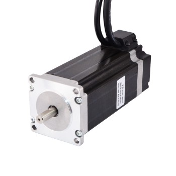
The rotor of an internal rotor motor is assembled inside the motor housing and connected to the motor’s output shaft. The rotor of an external rotor motor is located outside the motor, and the output shaft is also transmitted by the rotation of the rotor outside the motor.
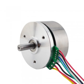
external rotor motors
                            external rotor motors

2.Differences in characteristics
1.Internal rotor motors are usually more compact and have higher power density because the motor components are more compact. External rotor motors are usually easier to maintain because the rotor components are outside the motor and are easy to maintain and replace.
2.Internal rotor motors can withstand higher pressures and torques because their rotors are more secure inside the motor. However, external rotor motors can rotate faster because their rotors are lighter.
3.Internal rotor motors tend to have longer life and higher efficiency than external rotor motors. This is because the rotor runs inside the motor and is not affected by external physical factors. The centripetal force and other physical phenomena generated by the external rotor motor when rotating at high speed may reduce the motor efficiency and life.

3.Application differences
Internal rotor motors are often used in high-performance applications such as aircraft, rockets, high-speed trains, etc. This is because internal rotor motors have higher power density and can provide greater output power. External rotor motors are usually used in smaller applications, such as household appliances, small machinery, etc. This is because they are easier to maintain and replace and have better reliability.

4.Summary
Both internal rotor motors and external rotor motors are important types of motors. According to different application environments and requirements, you can choose the appropriate motor type. Internal rotor motors are suitable for high-load and high-performance applications, while external rotor motors are suitable for smaller and simpler applications. In addition, internal rotor motors usually have higher efficiency and longer life, but external rotor motors are easier to maintain and replace.
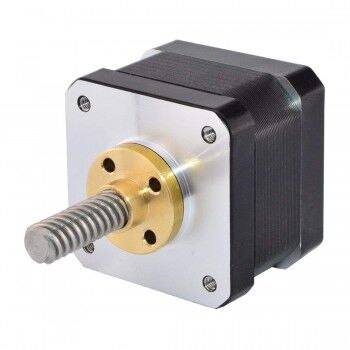
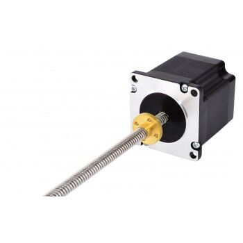
Linear stepper motor selection parameter reference

The linear stepper motor is generated by the interaction between the magnetic rotor core and the pulsed electromagnetic field generated by the stator. The linear stepper motor converts the rotary motion into linear motion inside the motor. But how to select the linear stepper motor? You can refer to the operating parameters of the motor
直线步进电机1

The following are the commonly used parameters of linear stepper motors
1.Maximum speed: The maximum operating speed under the determined power supply line voltage, depends on the number of back electromotive force lines of the motor, and reflects the result of the motor electromagnetic design.
2.Maximum thrust: The peak thrust of the motor, short-term, second level, depends on the safety limit capacity of the motor electromagnetic structure.
3.Maximum current: The maximum working current, corresponding to the maximum thrust, is lower than the demagnetization current of the motor.
4.Maximum continuous power consumption: Under the conditions of temperature rise and heat dissipation, the upper limit of the heat loss that the motor can continuously operate reflects the thermal design level of the motor.
5.Maximum voltage: The maximum power supply line voltage, mainly related to the insulation capacity of the motor.
6.Motor force constant: The thrust-to-current ratio of the motor, unit N/A or KN/A, reflects the result of the motor electromagnetic design, and in a sense, it can also reflect the electromagnetic design level.
直线步进电机2

7.Motor constant: The ratio of the motor thrust to the square root of power consumption, unit N/√W, is a comprehensive reflection of the motor electromagnetic design and thermal design level.
8.Back electromotive force : Motor back electromotive force (coefficient), unit Vs/m, reflects the result of the motor electromagnetic design, affecting the maximum operating speed of the motor under a certain supply voltage.
9.Motor attraction: For flat-type linear motors with iron core structure, especially permanent magnet motors, the normal attraction of the secondary permanent magnet to the primary iron core is one order of magnitude higher than the rated thrust of the motor, which directly determines the load-bearing capacity and selection of the support guide rails of the linear motion axis using the linear motor.

In summary, the selection of linear stepper motors is a process that takes into account multiple factors, including load specifications, stroke, speed, torque, speed, no-load starting frequency, phase selection, and motor selection under special environments.

Source:https://steppermotor1.livedoor.blog/archives/3241922.html

Detailed explanation of stepper motor driver interface

1. Stepper signal interface
The stepper signal interface of the ​stepper motor driver​ mainly receives the pulse signal sent by the controller and controls the motor to rotate according to a certain number of steps. It includes pulse signal, direction signal and enable signal. The pulse signal is the main signal to control the rotation of the motor, the direction signal is used to control the forward and reverse rotation of the motor, and the enable signal is used to control the motor to enable or disable. It should be noted that the pin number of each interface may be different, and it must be wired according to the actual interface.
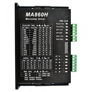
MA860H Stepper Motor Driver 2.4-7.2A Max 80VAC or 110VDC for Nema 17-Nema 42 Stepper Motor
2. Power interface
The power interface of the stepper motor driver is the main interface for receiving power input. It is necessary to pay attention to the voltage, current and other parameters of the interface. When wiring, the polarity of the power supply should be confirmed to avoid burning the driver due to wrong connection.
3. Control interface
The control interface of the stepper motor driver receives the command sent by the controller to control the movement of the motor. The control interface generally includes serial port, parallel port, network interface, etc., which needs to be selected according to the actual use environment.
4. Protection interface
The protection interface of the stepper motor driver generally includes protection mechanisms such as overcurrent protection and overvoltage protection. When the working current or voltage of the motor exceeds the preset value, the protection interface will automatically stop the motor to avoid damage to the entire circuit. Therefore, the protection interface is a very important part of the stepper motor driver.
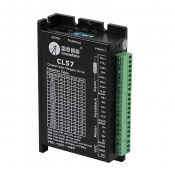
Leadshine CL57 Closed Loop Stepper Driver 0-8.0A 24-48VDC for Nema 17, Nema 23, Nema 24 Stepper Motor
5. Other interfaces
In addition to the above 4 main interfaces, the stepper motor driver has some other interfaces, such as limit interface, encoder interface, etc. The limit interface can be used to control the stroke of the motor. When the motor turns to the preset position, it will trigger the limit switch to stop the motor movement. The encoder interface can be used to feedback the state of the motor movement in real time, so as to control the motor movement more accurately.
In short, each interface of the stepper motor driver plays an important role and is crucial. Therefore, when using the stepper motor driver, it is necessary to carefully understand the role and use of each interface, and perform correct wiring operations according to the actual situation to ensure the safe and stable operation of the motor.

How Encoders Control Stepper Motors

1. What is a stepper motor encoder?

stepper motor encoder is a device used to measure output speed and position. It detects the rotation of the rotor through an internal sensor to output a pulse signal to achieve high-precision measurement and control of position and angle.

2. The principle of encoder control of stepper motors

Stepper motor encoders can play a very critical role in stepper motor control systems. By connecting the encoder to the shaft of the stepper motor driver, the movement of the stepper motor can be monitored and controlled. The encoder can compare the actual position with the information generated by the magnetic encoder and output a difference signal to achieve fine control through a feedback mechanism. In general, the encoder is used in conjunction with a stepper motor to achieve operations such as motion positioning or speed control.

stepper motor encoder

3. How to use encoders to control stepper motors in practical applications?

In the process of using encoders to control stepper motors, the following points need to be noted:

1. First, it is necessary to clarify the speed and position control parameters of the stepper motor, and select a suitable encoder model for connection and installation. Generally speaking, the encoder model should match the stepper motor control system.

2. When installing the encoder, the distance between the encoder and the stepper motor should be minimized as much as possible to reduce the impact of errors and signal delays.

3. When installing the encoder, you also need to consider the length and impedance matching of the signal line. Try to shorten the signal transmission distance and reduce signal noise and interference.
4. When using the encoder to control the stepper motor, you need to select the appropriate encoder pole number and output resolution according to the specific application scenario and requirements.

4. Conclusion
The encoder can control the stepper motor. The encoder and the stepper motor can be used together to achieve the position and speed control of the stepper motor. However, in actual applications, the encoder needs to be installed and configured according to the specific situation to achieve a more accurate and stable control effect.

Source:https://blog.aujourdhui.com/tianqiong2019/2705054/how_encoders_control_stepper_motors.html

What is a Pancake Stepper Motor?


1. Overview of Pancake Stepper Motor

A pancake stepper motor is a special motor that uses electric pulses to control the motor steps. Its structure is similar to that of a DC motor. The pancake stepper motor consists of a stator, a rotor, an end cover, a rotor shaft, front and rear plates, and a stator coil.

2. Functions of Pancake Stepper Motor

1. High precision: Pancake stepper motors can achieve precise steps according to the control signal. They have the characteristics of high precision, fast response, and strong stability. They are widely used in mechanical equipment with high precision requirements.

2. High horsepower: Pancake stepper motors will generate a large torque when running, which can provide sufficient driving force for mechanical equipment. They are suitable for heavy loads, low speeds, and high starting torque requirements.

3. Simple control: The control signal of the pancake stepper motor only needs to output electric pulses, which is simple and convenient to control. In addition, it can also achieve small step control, providing more accurate motion control for mechanical equipment.

4. High reliability: Pancake stepper motors are not easy to damage, have a long life, and are highly reliable.

3. Application of Pancake Stepper Motor

Pancake stepper motor has the characteristics of high precision, high horsepower, simple control and high reliability. It is widely used in robots, automation equipment, medical equipment and other fields to provide power for the movement of mechanical equipment and realize the efficient operation of mechanical equipment.

4. Conclusion

In short, pancake stepper motor is a motor with high control precision, high horsepower, simple control and high reliability. It has a wide range of application prospects and plays a very important role in mechanical equipment. It can improve the operation accuracy and efficiency of the equipment and provide strong power for the operation of mechanical equipment.

See more:https://www.oyostepper.com/